Les cellules PID jouent un rôle clé dans la détection de gaz des services d'incendie, municipalités, équipes d'intervention d'urgence et toutes sortes d'industries qui ont besoin d'un moyen rapide de confirmer la présence de composés organiques volatils (COV) dans l'atmosphère ou de localiser la source d'une fuite.
Avant d'utiliser une cellule PID pour détecter les COV, vous devez comprendre son fonctionnement afin de savoir à quoi vous attendre.
Sans plus attendre, commençons par une rapide leçon de chimie (et de physique).
La cellule PID cible les gaz au niveau moléculaire, et les molécules sont un groupe d'atomes liés entre eux par des liaisons. La force de ces liaisons est mesurée en électronvolts (eV) et est appelée potentiel d'ionisation (PI) de la molécule. Ce chiffre figure dans la description physique de pratiquement tous les gaz. Par exemple, le propane a un PI de 11,07 eV. Celui de l'ammoniac est de 10,2eV et celui du toluène de 8,82eV.
Cette information est importante car l'IP d'un gaz donné indique si une cellule PID peut détecter sa présence dans l'atmosphère.
Comment une cellule PID détecte-t-elle les COV ?
Les cellules PID contiennent une lampe UV qui libère une certaine énergie de ses photons. Lorsque cette énergie est suffisamment forte, elle déchire les liaisons de la molécule exposée, ce qui sépare ses atomes et les transforme en ions chargés positivement. Dans le même temps, des électrons sont déchargés en tant que sous-produits. La lampe UV a donc ionisé la molécule grâce à l'énergie de ses photons. Cette réaction en chaîne est appelée photoionisation.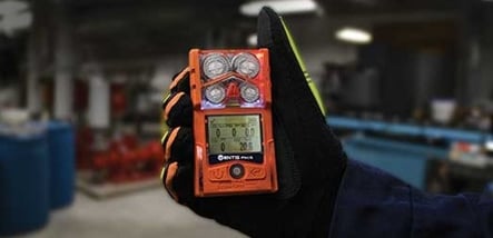 La cellule PID contient également un ensemble d'électrodes positives et négatives. Comme nous le savons, les opposés s'attirent. L'électrode positive attire donc les électrons (qui sont chargés négativement) et l'électrode négative attire les ions chargés positivement (également connus sous le nom de protons). Cela crée un petit courant qui est amplifié et converti par le détecteur de gaz en une lecture en ppm (parties par million).
Par conséquent, vous devez connaître l'énergie de votre lampe PID pour identifier les gaz qu'elle détectera ou ne détectera pas. Les cellules PID Industrial Scientific utilisent une lampe de 10,6 eV, ce qui signifie qu'elles peuvent détecter tout gaz dont l'IP est égal ou inférieur à 10,6 eV.
Étalonnage d'une cellule PID
Comme pour tout détecteur de gaz, un étalonnage régulier est essentiel pour garantir la précision des relevés d'une cellule PID. Mais si la cellule PID n'est pas spécifique à un seul gaz cible, quel gaz utilise-t-on pour l'étalonner ? Le choix standard est l'isobutylène, pour deux raisons :
- L'isobutylène n'est ni toxique ni combustible à de faibles concentrations.
- L'IP de l'isobutylène se situe au point médian de la plupart des COV.
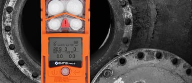
Pour connaître la concentration réelle du gaz qui a déclenché la lecture, il faut multiplier la lecture du détecteur de gaz par le facteur de réponse du gaz ciblé. Avec la cellule PID Industrial Scientific utilisée dans le détecteur multigaz Ventis Pro5®, il est possible de préprogrammer le détecteur de gaz pour qu'il applique automatiquement le facteur de réponse d'un gaz cible, ce qui évite les calculs mentaux.
Utilisation d'une cellule PID
Il est facile de parcourir la longue liste de gaz que la cellule PID peut détecter, de trouver le gaz que vous devez cibler et de conclure que la cellule PID est le bon choix pour vous. Ce qu'il est important de comprendre, c'est que la cellule PID ionise tous les gaz qu'elle est capable d'ioniser, ce qui vous donne une seule lecture cumulée de tous ces différents gaz. Elle ne peut pas les distinguer, ni en filtrer certains, ni en introduire d'autres. Il vous dira seulement s'il y a quelque chose dans l'atmosphère ou non et vous aidera à localiser la source d'une fuite.

La cellule PID en action
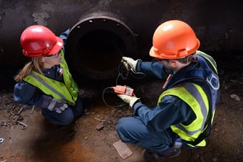
Une usine de fabrication utilise de grandes quantités de toluène comme solvant dans son processus. Le personnel a été informé d'une odeur anormalement forte. Il soupçonne une fuite de toluène. La zone est immédiatement évacuée, l'équipe d'intervention d'urgence du site est déployée pour contenir la fuite, et l'équipe de lutte contre les matières dangereuses des pompiers locaux est appelée pour aider à mettre en place les zones et à localiser la source de la fuite à l'aide de leurs détecteurs PID.
Comme indiqué précédemment, l'IP du toluène n'est que de 8,82 eV, ce qui signifie que la cellule PID Industrial Scientific le détectera. L'équipe de lutte contre les matières dangereuses apporte avec elle des détecteur multigaz Ventis Pro5 contenant plusieurs cellules, dont une PID étalonnée pour l'isobutylène. Compte tenu de l'urgence, ils décident de ne pas programmer le facteur de réponse au toluène directement sur leurs détecteurs. Ils savent que le facteur de réponse pour le gaz toluène est x0,56, donc si la cellule PID affiche 100 ppm, l'utilisateur saura qu'il y a environ 100x 0,56 = 56 ppm de toluène dans l'atmosphère. Dans cet exemple, le facteur de réponse peut être arrondi à la moitié de la valeur de la lecture du détecteur de gaz, ce qui facilite les calculs.
Lorsque l'équipe de lutte contre les matières dangereuses arrive, le groupe d'intervention d'urgence du site a réussi à contenir la fuite. Il est maintenant temps d'établir les zones. Grâce à la nature de la cellule PID, son temps de réponse est instantané. Il est donc facile d'identifier si l'on se dirige vers la source de la fuite ou si l'on s'en éloigne. À l'aide des détecteurs Ventis Pro5, l'équipe d'intervention fait le tour de la zone, en prêtant une attention particulière aux relevés de leurs cellules PID. L'un d'entre eux identifie rapidement la zone chaude car ses relevés atteignent soudainement un pic. En fait, la cellule PID est en dépassement d'échelle. Cela indique que les relevés sont supérieurs à 2 000 ppm, ce qui signifie qu'il y a plus de 1 120 ppm de toluène dans cette zone.
C'est le moment pour une autre cellule clé de briller : la cellule infrarouge d'hydrocarbures (HC) à très faible puissance (ULP). Pour faire simple, cette cellule utilise la technologie infrarouge pour détecter la présence d'hydrocarbures dans l'atmosphère. Mesurant de 0 à 100 % de la LIE, il indique si la zone est exposée à un risque de combustion, jouant un rôle similaire à celui de la cellule à diffusion catalytique classique. L'avantage de la cellule IR ULP HC est qu'elle prolonge la durée de vie de la batterie du détecteur, ce qui permet de configurer le Ventis Pro5 à la fois avec une PID et une cellule de gaz combustible. Elle ne s'abîme pas non plus lorsqu'elle est régulièrement exposée à des concentrations excessivement élevées, à des poisons ou à des inhibiteurs.
Revenant sur les lieux de la fuite, l'utilisateur s'enfonce davantage dans la zone chaude et la cellule ULP HC IR monte jusqu'à 100 % de la LIE. Il est lui aussi en dépassement de portée, ce qui indique qu'il doit se rapprocher de la source. Et juste là, le long de la partie inférieure du tuyau de toluène, se trouve une section fissurée, résultat évident d'une corrosion excessive.
Comme ils utilisent des détecteurs Ventis Pro5, les membres de l'équipe de lutte contre les matières dangereuses sont reliés entre eux par LENS Wireless, ce qui leur permet de voir en temps réel les relevés de leurs collègues sur leurs propres moniteurs. Ils avertissent l'équipe d'intervention d'urgence, qui se met en route pour remédier à la fuite.
Que deviennent les vapeurs de toluène qui ne se sont pas encore dissipées ? L'équipe de lutte contre les matières dangereuses déploie des détecteurs de zone portables Radius® BZ1 qui sont non seulement équipés de cellules PID, mais aussi d'une fonction sans fil LENS, tout comme les détecteurs portables Ventis Pro5, ce qui permet une communication entre toutes les unités PID sur le terrain.
En tenant compte de la direction du vent, ils placent stratégiquement les détecteurs de zone de manière à pouvoir suivre en continu les niveaux de toluène dans toutes les zones. L'ERT utilisera également des détecteurs Ventis Pro5 jusqu'à ce que le danger ait complètement disparu de l'atmosphère. Si l'un des détecteurs de zone déclenche une alarme, la fonctionnalité LENS Wireless permettra à l'utilisateur du Ventis Pro5 d'être immédiatement averti par le biais de son unité. En fait, il aura accès aux relevés de gaz actuels de tous les détecteurs de zone Radius BZ1 et des détecteurs multigaz Ventis Pro5 sur le terrain.
Enfin, l'équipe hazmat a mis en place des passerelles RGX qui permettront d'envoyer les données de l'équipement directement vers le Cloud pour une surveillance à distance en direct. L'ERT et le centre de contrôle peuvent désormais surveiller en direct les relevés de tous les détecteurs de gaz sur le terrain à partir d'un navigateur et recevoir les alertes en temps réel, quelle que soit la distance qui les sépare du site.
Une fois le problème résolu, les pompiers récupèrent leur matériel et le préparent pour le prochain appel. Après cette expérience, l'usine de fabrication choisira probablement de s'équiper de ses propres détecteurs de gaz PID si un tel cas devait se reproduire sur son site.
Cet exemple illustre la manière dont une cellule PID peut être utilisée. Il met également en lumière la façon dont une cellule comme la PID peut débloquer de nouvelles possibilités dans le monde de la sécurité connectée.
En savoir plus sur la détection des COV à l'aide de la cellule PID.